Thursday, 23 May 2019

Levelling

Levelling


Levelling (or Leveling) is a branch of surveying, the object of which is: i) to find the elevations of given points with respect to a given or assumed datum, and ii) to establish points at a given or assumed datum. The first operation is required to enable the works to be designed while the second operation is required in the setting out of all kinds of engineering works. Levelling deals with measurements in a vertical plane.
Level surface: A level surface is defined as a curved surface which at each point is perpendicular to the direction of gravity at the point. The surface of a still water is a truly level surface. Any surface parallel to the mean spheroidal surface of the earth is, therefore, a level surface.
Level line: A level line is a line lying in a level surface. It is, therefore, normal to the plumb line at all points.
Horizontal plane: Horizontal plane through a point is a plane tangential to the level surface at that point. It is, therefore, perpendicular to the plumb line through the point.
Horizontal line: It is a straight line tangential to the level line at a point. It is also perpendicular to the plumb line.
Vertical line: It is a line normal to the level line at a point. It is commonly considered to be the line defined by a plumb line.
Datum: Datum is any surface to which elevation are referred. The mean sea level affords a convenient datum world over, and elevations are commonly given as so much above or below sea level. It is often more convenient, however, to assume some other datum, specially, if only the relative elevation of points are required.
Elevation: The elevation of a point on or near the surface of the earth is its vertical distance above or below an arbitrarily assumed level surface or datum. The difference in elevation between two points is the vertical distance between the two level surface in which the two points lie.
Vertical angle: Vertical angle is an angle between two intersecting lines in a vertical plane. Generally, one of these lines is horizontal.
Mean sea level: It is the average height of the sea for all stages of the tides. At any particular place it is derived by averaging the hourly tide heights over a long period of 19 years.
Bench Mark: It is a relatively permanent point of reference whose elevation with respect to some assumed datum is known. It is used either as a starting point for levelling or as a point upon which to close as a check.

Methods of levelling

Three principle methods are used for determining differences in elevation, namely, barometric levelling, trigonometric levelling and spirit levelling.

Barometric levelling

Barometric levelling makes use of the phenomenon that difference in elevation between two points is proportional to the difference in atmospheric pressures at these points. A barometer, therefore, may be used and the readings observed at different points would yield a measure of the relative elevation of those points.
At a given point, the atmospheric pressure doesn’t remain constant in the course of the day, even in the course of an hour. The method is, therefore, relatively inaccurate and is little used in surveying work except on reconnaissance or exploratory survey.

Trigonometric Levelling (Indirect Levelling)

Trigonometric or Indirect levelling is the process of levelling in which the elevations of points are computed from the vertical angles and horizontal distances measured in the field, just as the length of any side in any triangle can be computed from proper trigonometric relations. In a modified form called stadia levelling, commonly used in mapping, both the difference in elevation and the horizontal distance between the points are directly computed from the measured vertical angles and staff readings.

Spirit Levelling (Direct Levelling)

It is that branch of levelling in which the vertical distances with respect to a horizontal line (perpendicular to the direction of gravity) may be used to determine the relative difference in elevation between two adjacent points. A horizontal plane of sight tangent to level surface at any point is readily established by means of a spirit level or a level vial. In spirit levelling, a spirit level and a sighting device (telescope) are combined and vertical distances are measured by observing on graduated rods placed on the points. The method is also known as direct levelling. It is the most precise method of determining elevations and the one most commonly used by engineers.

Levelling Instruments

The instruments commonly used in direct levelling are:
  1. A level
  2. A levelling staff

Theodolite

Theodolite

Theodolite has many parts which needs to be adjusted every time while surveying. It is important to know about theodolite parts and their functions before using it to minimize errors during theodolite surveying.
Theodolite is an instrument used in surveying to measure horizontal and vertical angles. It is also used for leveling, indirect measure of distances and prolonging a line etc. The line of sight of theodolite can be rotated through 180o in vertical plane about its horizontal axis.

Parts of Theodolite and their Functions

Following are the parts of a theodolite:
  • Telescope
  • Vertical circle
  • Index frame
  • The standards
  • The upper plate
  • The lower plate
  • The leveling head
  • The shifting head
  • Plate level
  • Tripod
  • Plumb bob
  • Magnetic compass


Telescope

A telescope is a focusing instrument which has object piece at one end and eye piece at the other end. It rotates about horizontal axis in vertical plane. The graduations are up to an accuracy of 20’.

Vertical Circle

Vertical circle is fitted to telescope and moves simultaneously with telescope. It has graduation in each quadrant numbered from 0 to 90degrees.

Index Frame

It is also called as t-frame or vernier frame. It consists two arms vertical and horizontal. Vertical arm helps to lock the telescope at desired level and horizontal arm is useful to take the measurements of vertical angles.
 

The Standards

The standards are the frames which supports telescope and allow it to rotate about vertical axis. Generally, these are in letter A-shape. So, standards are also called as A-frame.

The Upper Plate

This is also called as vernier plate. The top surface of upper plate gives support to the standards. It also consists an upper clamping screw with respect to tangents screw which helps to fixing it to the lower plate.
When the upper clamping screw is tightened both upper and lower plates are attached and moved together with some relative motion because of upper tangent screw. The upper [late also consists two verniers with magnifiers which are arranged diagonally. It is attached tow inner spindle.

The Lower Plate

This is also called as scale plate. Because it contains a scale on which 0 to 360 readings are graduated. It is attached to the outer spindle and consists lower clamping screw. If lower clamp screw is loosened and upper clamp screw is tightened, both plates can rotate together.
Similarly, if lower clamping screw is tightened and upper clamp is loosened then, only upper plate is movable and lower plate is fixed with tribratch plate.

The Leveling Head

The leveling head contains two parallel triangular plates called as tribratch plates. The upper one is known as upper tribratch plate and is used to level the upper plate and telescope with the help of leveling screws provided at its three ends. The lower one is called as lower tribratch plate and is attached to the tripod stand.

The Shifting Head

Shifting head also contains two parallel plates which are moved one over the other with in small area. Shifting head lies below the lower plate. It is useful to centering the whole instrument over the station.

Plate Level

Plate levels are carried by the upper plate which are right angles to each other with one of them is parallel to trunnion axis. These plate levels help the telescope to settle in exact vertical position.

Tripod

Tripod is nothing but a stand on which theodolite is mounted. It should place in such a way that theodolite should be in exact leveled position. The tripod has legs with steel shoes at their ends. These hold the ground strongly without any movement when placed.
Tripod has an external screw which helps to attach the theodolite by tribratch plate in fixed position.

Plumb Bob

Plumb bob is tool having a cone shaped weight attached to a long thread. The weight is hanged using thread from the center of tripod stand and centering of theodolite is done.

Magnetic Compass

Simpler theodolites may contain circular compass box in the center of upper plate. When we select north as reference meridian it will be useful

Working of Vernier Theodolite

Working of a Vernier theodolite starts with setting up and adjustment of theodolite for the measurement of angles.

Temporary Adjustment of Theodolite

Following are the adjustment required for theodolite before using it:
  • Setting
  • Centering
  • Leveling
  • Focusing

Setting of Theodolite

Setting means attaching theodolite to the tripod stand. The tripod is unfolded and placed on the ground with all legs in same level. In this operation, we level the tripod by just eye estimation. From the bottom of theodolite, a plumb bob is suspended to set the instrument over station mark.


Centering

Centering is the process in which the vertical axis of the instrument is coincided with the plumb line. The legs of tripod stand should be of equal height on leveled ground and they have cone shape metal shoes which can easily hold the ground without any movement.
 

Leveling of Theodolite

Leveling of theodolite is completed by making the vertical axis of instrument truly vertical. It is done by centering the bubble in the level tube by rotating foot screws provided. The bubbling should be done in all direction of telescope and the centered bubble should not move while taking reading.


Focusing

Focusing is the adjustment of telescope to obtain clear visibility of image through eyepiece and objective lens. This process done by removing parallax error by proper focusing of eyepiece and objective lens.

Measurement of Horizontal Angle using Theodolite

After the temporary adjustment of theodolite, the telescope is located at a point from which we must focus the other point to find horizontal angle between them. Let us say A, B and C are three points on same ground level with some distances as shown in figure below. Now the angle ABC can be determined as below described procedure.

Procedure for Measurement of Horizontal Angle

  1. The instrument is located at point B with all temporary adjustments and ranging rods are located at points A and C.
  2. Now, set the Vernier A reading to zero and Vernier B reading to 180 by rotating telescope. This should be done by releasing the upper clamp screw and tightening of lower clamp screw.
  3. After setting the Vernier, tighten the upper clamp screw and check the reading without any error with the help of upper tangent screw.
  4. Whenever the upper clamp is tightly fixed, loosen the lower clamp screw it will allow the telescope to turn without any change in reading. Now focus the ranging rod at location A and bisect it.
  5. After bisecting A, release the upper clamp screw and rotate the telescope in clockwise direction towards ranging rod at C and bisect it. Now observe the Vernier reading which will be the horizontal angle between A and C or angle ABC.
  6. In the above explained case, the vertical circle is present left side of the telescope, then repeat the same procedure with vertical circle right side of telescope. The average value of angles obtained in face left and face right conditions gives more accurate value of horizontal angle.

Measurement of Vertical Angle using Theodolite


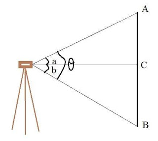
  1. After the temporary adjustment of theodolite, set Vernier reading of vertical circle to 0 using clamp screws and focus it to C.
  2. Center the bubble using foot screws without any collimation error. Then raise the telescope slowly towards point A as shown in fig. bisect the point A and note down the Vernier reading angle AOC.
  3. Similarly bisect the point B from C after which will give angle BOC. Now we can compute the angle AOB.
  4. Conduct the procedure in both face left and face right conditions and the average value is considered as accurate vertical angle

Compass surveying

Compass surveying

Compass surveying is the branch of surveying in which the position of an object is located using angular measurements determined by a compass and linear measurements using a chain or tape. Compass surveying is used in following circumstances:
  • If the surveying area is large, chain surveying is not adopted for surveying rather compass surveying is employed.
  • If the plot for surveying has numerous obstacles and undulations which prevents chaining.
  • If there is a time limit for surveying, compass surveying is usually adopted.

Compass surveying is not used in places which contain iron core, power lines etc which usually attracts magnets due to their natural properties and electromagnetic properties respectively. Compass surveying is done by using traversing. A traverse is formed by connecting the points in the plot by means of a series of straight lines.
 

Magnetic compass

Magnetic compass is used to find out the magnetic bearing of survey lines. The bearings may either measured in Whole Circle Bearing (W.C.B) system or in Quadrantal Bearing (Q.B) system based on the type of compass used. The basic principle of magnetic compass is if a strip of steel or iron is magnetized and pivoted exactly at centre so that it can swing freely, then it will establish itself in the magnetic meridian at the place of arrangement.
Major types of magnetic compass are:
  1. Prismatic compass
  2. Surveyor’s compass
  3. Level compass

Prismatic compass

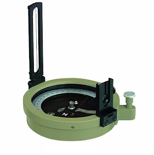
Prismatic compass is a portable magnetic compass which can be either used as a hand instrument or can be fitted on a tripod. It contains a prism which is used for accurate measurement of readings. The greatest advantage of this compass is both sighting and reading can be done simultaneously without changing the position.

Major parts of a Prismatic Compass are:

  • Magnetic needle
  • Graduated ring
  • Adjustable mirror
  • Sliding arrangement for mirror
  • Object vane
  • Eye vane
  • Metal box
  • Glass cover
  • Horse hair

Adjustments of prismatic compass

Two types of adjustments:
  1. Temporary adjustment
  2. Permanent adjustment

Temporary adjustments

  • Centering: it is the process of fixing the compass exactly over the station. Centering is usually done by adjusting the tripod legs. Also a plumb-bob is used to judge the accurate centering of instruments over the station.
  • Leveling: the instrument has to be leveled if it is used as in hand or mounted over a tripod. If it is used as in hand, the graduated disc should swing freely and appears to be completely level in reference to the top edge of the case. If the tripod is used, they usually have a ball and socket arrangement for leveling purpose.
  • Focusing the prism: Prism can be slide up or down for focusing to make the readings clear and readable.
Permanent adjustments are same as in the Surveyor’s compass.

Surveyor’s compass

Surveyor’s compass consists of a circular brass box containing a magnetic needle which swings freely over a brass circle which is divided into 360 degrees. The horizontal angle is measured using a pair of sights located on north – south axis of the compass. They are usually mounted over a tripod and leveled using a ball and socket mechanism.
Surveyor’s compass (National Museum of American History)
They also have two types of adjustments, temporary and permanent. Temporary adjustments are same as described in prismatic compass.
Permanent adjustments
They are done only in the circumstances where the internal parts of the prism is disturbed or damaged. They are:
  • Adjustments in levels
  • Adjustment of pivot point
  • Adjustment of sight vanes
  • Adjustment of needle

Advantages & Disadvantages of Compass surveying

Advantages

  • They are portable and light weight.
  • They have fewer settings to fix it on a station
  • The error in direction produced in a single survey line does not affect other lines.
  • It is suitable to retrace old surveys.

Disadvantages

  • It is less precise compared to other advanced methods of surveying.
  • It is easily subjected to various errors such as errors adjoining to magnetic meridian, local attraction etc.
  • Imperfect sighting of the ranging rods and inaccurate leveling also causes error.

Errors in compass survey

Errors can be arising due to various reasons during the process of surveying, they are classified as:
  • Instrumental errors
  • Personal errors
  • Natural errors

Instrumental errors

As the name suggests they are arise due to the wrong adjustments of the instruments. Some other reasons are:
  • If the plane of sight not being vertical, it causes error in sighting and reading.
  • If the magnetic needle is not perfectly straight or if it is sluggish, readings may not be accurate.

Personal errors

They arise mainly due to the carelessness of the surveyor. They are:
  • Inaccurate leveling
  • Inaccurate reading
  • Inaccurate centering

Natural errors

Natural errors are occurring due to the various natural causes which affect the working of compass. It has nothing to do with the surveyor and to minimize them, some corrections in calculations applied. They are:
  • Local attraction
  • Proximity to the magnetic storms
  • declination

Surveying and Principle

What is Surveying?

Surveying is the technique of determining the relative position of different features on, above or beneath the surface of the earth by means of direct or indirect measurements and finally representing them on a sheet of paper known as plan or map.

Surveying is primarily classified as under:
  1. Plane surveying
  2. Geodetic Surveying
Plane Surveying is that type of surveying in which the mean surface of the earth is considered as a plane and the spheroidal shape is neglected. All triangles formed by survey lines are considered plane triangles. The level line is considered straight and all plumb lines are considered parallel. In everyday life were are concerned with small portion of earth’s surface and the above assumptions seems to be reasonable in light of the fact that the length of an arc 12 kilometers long lying in the earth’s surface is only 1cm greater than the subtended chord and further that the difference between the sum of the angles in a plane triangle and the sum of those in a spherical triangle is only one second for a triangle at the earth’s surface having an area of 195 sq. km.
Geodetic Surveying is that type of surveying in which the shape of the earth is taken into account. All lines lying in the surface are curved lines and the triangles are spherical triangles. It therefore, involves spherical trigonometry. All Geodetic surveys include work of larger magnitude and high degree of precision. The object of geodetic survey is to determine the precise position on the surface of the earth, of a system of widely distant points which form control stations to which surveys of less precision may be referred.

Classification of surveying

Surveys may be secondarily classified under no. of headings which define the uses or purpose of resulting maps.

Classification based upon nature of field:

There are three types of surveying based upon the nature of field which are as follows:
  1. Land Surveying: It can be further classified as i) Topographical survey ii) Cadastrial Survey and iii) City Survey. It generally deals with natural or artificial features on land such as rivers, streams, lakes, wood, hills, roads, railways, canals, towns, water supply systems, buildings & properties etc.
  2. Marine Surveying: Marine or hydrographic survey deals with bodies of water for purpose of navigation, water supply, harbour works or for determination of mean sea level. The work consists in measurement of discharge of streams, making topographic survey of shores and banks, taking and locating soundings to determine the depth of water and observing the fluctutations of the ocean tide.
  3. Astronomical Surveying: The astronomical survey offers the surveyor means of determining the absolute location of any point or the absolute location of and direction of any line on the surface of the earth. This consists in observations to the heavenly bodies such as the sun or any fixed star.

Classification based on object:

Based on object, there are four types of surveying which are as follows:
  1. Geological Surveying
  2. Mine Surveying
  3. Archaeological surveying
  4. Military surveying

Classification based on instruments used:

Based on various types of instruments used, surveying can be classified into six types.
  1. Chain surveying
  2. Compass surveying
  3. Plane table surveying
  4. Theodolite surveying
  5. Tacheometric surveying
  6. Photographic surveying

Classification based on methods used:

Based on methods adopted, surveying can be categorized into:
  1. Triangulation surveying
  2. Traverse surveying

Principles of Surveying

The fundamental principle upon which the various methods of plane surveying are based can be stated under the following two aspects.

1)Location of a point by measurement from two points of reference

According to this principle, the relative position of a point to be surveyed should be located by measurement from at least two points of reference, the positions of which have already been fixed.
 
If P and Q are the two reference points on the ground, any other point, such as R, can be located by any of the direct methods shown in the above figures. But, although a single method is sufficient to locate the relative position of ‘R’ with respect to reference points P and Q, it is necessary to adopt at least any two methods to fix the position of point ‘R’.
While the measurements made in the either of the first method or second method will be helpful in locating the point ‘R’, the measurements made in the other method will act as a check.

2)Working from whole to part


According to this principle, it is always desirable to carryout survey work from whole to part. This means, when an area is to be surveyed, first a system of control points is to be established covering the whole area with very high precision. Then minor details are located by less precise methods.
The idea of working this way is to prevent the accumulation of errors and to control and localize minor errors which, otherwise, would expand to greater magnitudes if the reverse process is followed, thus making the work uncontrolled at the end

Tacheometric Surveying


Tacheometric Surveying- Methods, Detail Procedure

Tacheometry is a branch of angular surveying in which the horizontal and vertical distances are obtained by optical means as opposed to the ordinary process of chain and tape. This is done with the help of two special type of instruments- transit theodolite and stadia rod. On the other hand, other conventional surveying methods like chain surveying or traverse surveying need the surveyor to take a linear measurement on the field by a tape or a chain. These are relatively slower processes and also tiresome.

Tacheometric Surveying Instruments

Tacheometric Surveying is done with the help of Tacheometer and Stadia Rod. To read details of the tacheometric surveying instruments click the following link:
  1. Tacheometer
  2. Stadia Rod
  3. Anallatic lens

Different Methods of Tacheometric Measurements

The various methods of the tacheometric survey may be classified as follows:
  1. The Stadia System
    1. Fixed Hair Method
    2. Movable Hair Method, or Subtense Method
  2. The Tangential System
  3. Measurements by means of Special Instruments
A brief description of these methods is given below.

Fixed Hair Method

  • In this method, the angle at the instrument at A subtended by a known short distance along a staff kept at B is made with the help of a stadia diaphragm having stadia wires at fixed or constant distance apart.
  • The readings are on the staff corresponding to all the three wires taken.
  • The staff intercept which means the difference of the readings corresponding to the top and bottom stadia wires will, therefore, depend on the distance of the stadia/level staff from the tacheometer
  • When the staff intercept is more than the length of the staff, the only half intercept is read.
  • This is the most common method is tacheometry and the same ‘stadia method’ generally bears reference to this method.

Subtense Method

  • This method is almost same as the stadia method except that the stadia interval is variable.
  • A suitable arrangement is made to vary the distance between the stadia hair as to set them against the two targets on the staff kept at the point under observation.
  • Thus, in this case, the staff intercept, i.e., the distance between the two targets is kept fixed while the stadia interval, i.e., the distance between the stadia hair is variable.
  • As in the case of fixed hair method, inclined sights may also be taken.

Stadia Method

As in the field of tacheometric surveying ‘Stadia Method’ is the most widely used procedure so we will discuss the principle behind it. The stadia method follows the principle that in similar isosceles triangles the ratio of the perpendicular to the base is constant.
In fig. let two rays be equally inclined to the central ray. Here central ray is shown as OC. A2B2, A1B1, and AB are staff intercepts i.e difference between upper and lower stadia reading.
Evidently, OC2/A2B2= OC1/A1B1= OC/AB= constant K= 0.5cot (β/2)
This constant depends entirely on the angle β. Let, the constant is found to be 100. It means the distance between the staff and the point O will be 100 times the staff intercept.

The Distance-Elevation Formulae For Horizontal Sight

Suppose,
the interval between stadia hairs is given by i=ab,
staff intercept is s,
f is the focal length of the objective,
D is the horizontal distance of the staff from the vertical axis of the instruments.
The horizontal distance between the axis and the staff is given by the following equation
D = f1 + d= f1= (s/i)*f+(f+d)
This is the distance equation. Staff intercept is found by subtracting the reading of the upper and lower stadia reading.
The constant k = f/i is called the multiplying constant or stadia interval factor and the constant (f + d) =C is known as the additive constant of the tacheometer but the latter one is made zero by using an anallatic lens in the instrument.

Determination of Tacheometric Constants on Field

In most cases, we do not really know the value of f (focal length of the objective) so we have to determine the constant k and C on the field with a different approach as below:
  1. Measure a line (about 100m long) on the fairly level ground and drive pegs at some interval, say 50 meters.
  2. Keep the staff on the previously determined station and observe the corresponding staff intercepts (upper and lower stadia reading) with horizontal sight.
  3. Knowing the values of D and s for different points, a number of simultaneous equations can be formed by substituting the values of D and s in equation D = k.s + C. The simultaneous solution of successive pairs will give the values of k and C, and the average of these can be found.